Fan Coil Unit
Circular Cassette Type
We aim to promote Korea's air conditioning technology worldwide
and grow into a globally competitive company through sustainable innovation.

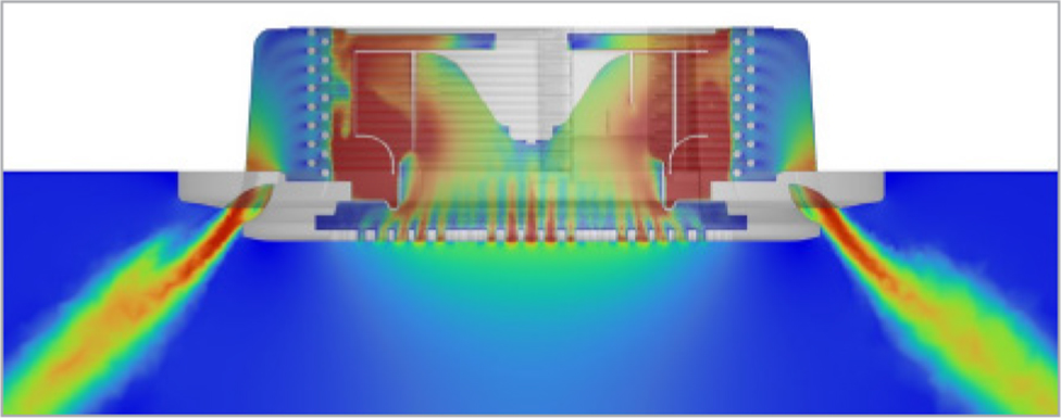
Velocity Distribution Specified : 0~10m/s
Results : Fluids drawn in by the circular cassette are forcibly driven by the rotating fan, resulting in high flow rates due to the forced convection device. The fluid exiting the fan undergoes deceleration due to the large surface area before being discharged, causing an increase in flow rate.
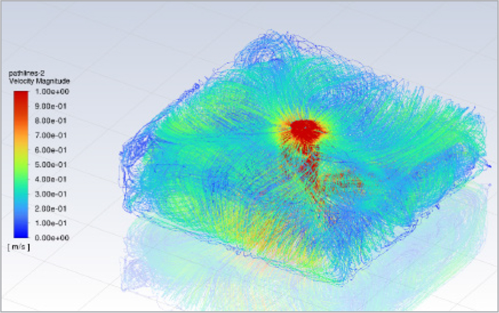
Initial Settings : 0-2 m from the ground → 20°C, 2-3 m →40°C
Results : As the air conditioner operates, the internal flows are mixed, resulting in a uniform temperature distribution overall. Over time, it can be observed that the internal temperature gradually decreases. The results above show the velocity distribution in the indoor space over time.
High velocity is formed from the fan to the floor, and then the velocity continues to circulate from the floor, spreading throughout the indoor space.
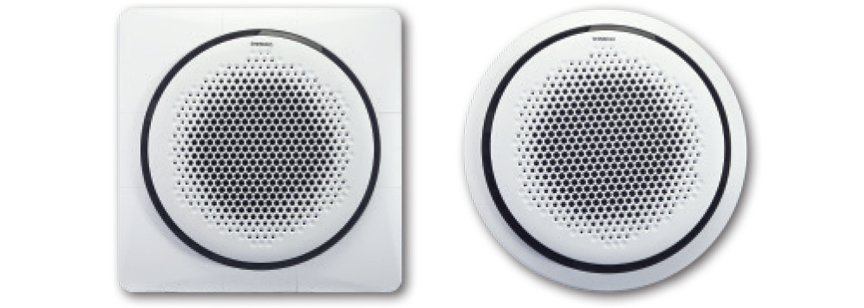
Both the circular grille (exposed installation) and the square grille (concealed installation) are available, depending on the installation location
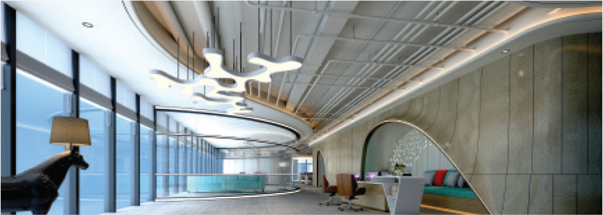
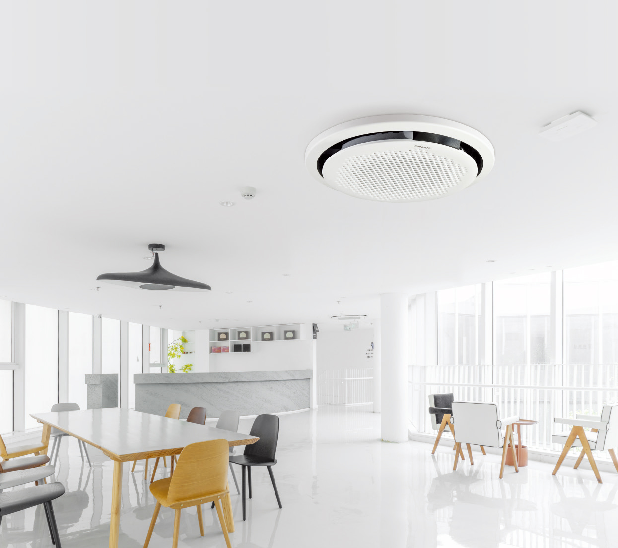
Interior panel that harmonizes with non-linear interior designs → A circular design that blends harmoniously with any space
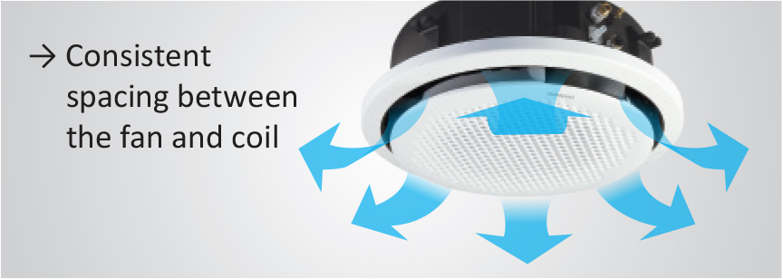
The airflow direction is 360°, With the airflow evenly distributed without blind spots, ensuring smooth cooling and heating.

With the application of a new separate and dedicated fan, quieter and more powerful airflow is secured. It offers three levels of strength (high, medium, low) and a turbo function for rapid cooling and heating.

With the use of a patented sterilization device, it has excellent effects in sterilization, antibacterial action, odor removal, and addressing sick building syndrome, without deteriorating heating and cooling performance.Option

With the application of a DC drain pump, low noise, low vibration, and a high head (1.2M) are achieved. When a proportional control valve is applied, the return power of the heat source supply pump can be reduced by controlling the flow rate according to the set temperature.

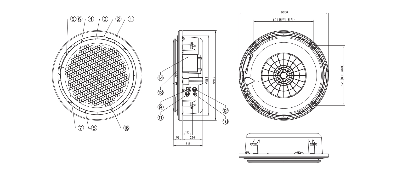
| No. | DESCRIPTION | MAT'L | Q'TY | REMARK |
|---|---|---|---|---|
| 1 | INTERIOR GRILLE ASS'Y | ABS | 1 | - |
| 2 | DRIAN PAN | ABS | 1 | SLIDING TYPE |
| 3 | BLADE | ABS | 4 | - |
| 4 | RETURN GRILLE | ABS | 1 | - |
| 5 | DRAIN PUMP | ASS'Y | 1 | - |
| 6 | FLOAT S/W | ASS'Y | 4 | DC12V |
| 7 | REMOTE CONTROL RECEIVER | - | 1 | - |
| 8 | STEPPING MOTOR | ASS'Y | 4 | DC12V, 15Ω |
| 9 | DRAIN PIPE PORT | - | 1 | Ø16 (Outer Diameter) |
| 10 | AIR VENT | ASS'Y | 1 | PT 1/4" (Manual) |
| 11 | WATER INLET | BS | 1 | PF 3/4" (20A) |
| 12 | WATER OUTLET | BS | 1 | PF 3/4" (20A) |
| 13 | INNER GUIDE | EPS | 1 | - |
| 14 | CONTROL BOX | ABS | 1 | - |
| 15 | ACCESS DOOR | ABS | 4 | - |
| 16 | FAN & MOTOR | ASS'Y | 1 | - |
| Category | Specifications | SFC-R3K | SFC-R4K | SFC-R5K | SFC-R6K | SFC-R8K | SFC-R10K | |||||||
|---|---|---|---|---|---|---|---|---|---|---|---|---|---|---|
| Capacity | Capacity Conditions | A | B | A | B | A | B | A | B | A | B | A | B | |
| Cooling Capacity | W | 5,210 | 3,900 | 6,100 | 4,590 | 8,390 | 6,390 | 10,090 | 7,610 | 13,180 | 9,890 | 15,660 | 11,630 | |
| Kcal/h | 4,480 | 3,360 | 5,240 | 3,950 | 7,210 | 5,500 | 8,680 | 6,550 | 11,330 | 8,510 | 13,460 | 10,000 | ||
| Heating Capacity | W | 9,860 | 5,950 | 11,530 | 6,980 | 15,560 | 9,530 | 18,460 | 11,220 | 23,840 | 14,470 | 28,780 | 17,270 | |
| Kcal/h | 8,480 | 5,120 | 9,910 | 6,000 | 13,380 | 8,200 | 15,880 | 9,650 | 20,500 | 12,440 | 24,750 | 14,850 | ||
| Flow Rate | ℓ/min | 15.0 | 11.2 | 17.5 | 13.2 | 24.1 | 18.4 | 28.9 | 21.8 | 37.8 | 27.8 | 44.9 | 33.3 | |
| Head Loss | mAq | 3.6 | 2.0 | 4.9 | 2.8 | 2.4 | 1.4 | 3.4 | 2.0 | 5.7 | 3.1 | 8.1 | 4.5 | |
| Fan Blower | Type | Single Suction TURBO type | ||||||||||||
| SIZE | mm | Ø480 | ||||||||||||
| Airflow Volume | ㎥/min | 13 | 16 | 19 | 22 | 28 | 33 | |||||||
| Drive Type | Direct Drive Motor | |||||||||||||
| Quantity | EA | 1 | ||||||||||||
| Motor | Type | BLDC: Enclosed Type (8 poles, Class E insulation) | ||||||||||||
| Power Consumption | W | 24 | 40 | 56 | 95 | 110 | 195 | |||||||
| Quantity | EA | 1 | ||||||||||||
| Heat Exchanger | Type | Integrated Multi-ass Cross Finned Tube (Slit Fin) | ||||||||||||
| Pipe | Inlet | A | PF 3/4" (20A) | |||||||||||
| Outlet | A | PF 3/4" (20A) | ||||||||||||
| Drain | Ø16 (Outer Diameter) / Built-in Drain Pump (10 W) / Head 600 mm (from Outlet) | |||||||||||||
| External Material | Main Body and Grille Panel: Injection Molded (ABS, Composite PP Material) | |||||||||||||
| Thermal Material | P.U Foam, P.E Foam, Styro Foam / Flame Retardant | |||||||||||||
| Air Volume Control | Turbo, Strong, Medium, Weak, Automatic Wireless Remote Controller (Wired remote controller is optional) | |||||||||||||
| Power Supply | Single Phase 220 V 60 HZ | |||||||||||||
| AIR FILTER | Vinyl Chloride (Submersible Type) | |||||||||||||
| Discharge Swing Motor | DC 12V STEPPING MOTOR | |||||||||||||
| Dimensions | Main Body | DxWxH (mm) |
880 x 240 | |||||||||||
| Panel | Ø960 x 240 (Rounded) / 1000 x 1000 x 74 (Squared) | |||||||||||||
| Product Weight | Kg | 16.9 / 18.0 | 19.7 / 20.8 | 22.4 / 23.5 | ||||||||||
| * Note | 1. Capacity Condition A - Cooling Capacity When indoor air is DB 27°C, WB 21°C, and inlet water temperature is 5°C Heating Capacity When indoor air is 18°C, and inlet water temperature is 80°C 2. Capacity Condition B - Cooling Capacity: When indoor air is DB 27°C, WB 19.5°C, and inlet water temperature is 7°C Heating Capacity: When indoor air is 21 °C, and inlet water temperature is 60°C |
|||||||||||||